550 Results
View results:
Sort by:
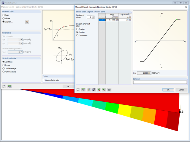
In the "Material Model - Isotropic Nonlinear Elastic" window, you can select the yield laws according to the von Mises, Tresca, Drucker-Prager, and Mohr-Coulomb yield rules. This makes it possible to describe the elasto-plastic material behavior. The yield function depends on the principal stresses or the invariants of a stress tensor. The criteria apply to 2D and 3D material models.
Structures react differently to wind action depending on stiffness, mass, and damping. A basic distinction is made between buildings that are prone to vibration and those that are not.
Computer technology has a firm grip on digital structural analysis and design. With each new development, the planners involved are able to increase the limits of what is feasible.
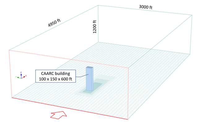
The following study compares the wind pressure on a tall building obtained by RWIND Simulation with the results published by Dagnew et al. at the 11th Americas Conference on Wind Engineering in June, 2009. In this paper, the Commonwealth Advisory Aeronautical Council (CAARC) building is used as a model, and the results of several different numerical methods are compared with experimental data obtained from wind tunnels.

When it comes to wind loads on building type structures as per ASCE 7, numerous resources can be found to supplement design standards and aid engineers with this lateral load application. However, engineers may find it more difficult to find similar resources for wind loading on non-building type structures. This article will examine the steps to calculate and apply wind loads as per ASCE 7-22 on a circular reinforced concrete tank with a dome roof.

When it comes to wind loads on building type structures as per ASCE 7, numerous resources can be found to supplement design standards and aid engineers with this lateral load application. However, engineers may find it more difficult to find similar resources for wind loading on non-building type structures. This article will examine the steps to calculate and apply wind loads as per ASCE 7-16 on a circular reinforced concrete tank with a dome roof.

In Germany, DIN EN 1991-1-4 with the National Annex DIN EN 1991-1-4/NA regulates the wind loads. The standard applies to civil engineering works up to an altitude of 300 m.

The Eurocode for DIN EN 1991‑1‑4:2010‑12 describes wind loads acting on structural systems.

Wind blowing parallel to the surfaces of a structure can generate friction forces on these surfaces. This effect is important mainly for very large structures.
Since wind on laterally open structures is not addressed in the Eurocode, the 4 cases of the German DIN 1055, Part 4 are referenced.
The wind loads are regulated according to Eurocode 1 - Actions on Structures - Part 1-4: General actions - Wind loads. The nationally determined parameters of a respective country can be found in the National Annexes.

Structures are naturally three-dimensional. However, because it was impossible to perform calculations on three-dimensional models easily in the past, the structures were simplified and broken down into planar subsystems. With the increasing performance of computers and related software, it is often possible to do without these simplifications. Digital trends such as Building Information Modeling (BIM) and new options for creating realistic visualized models reinforce this trend. But do 3D models really offer an advantage, or are we just following a trend? The following text presents some arguments for working in 3D models.

CFD calculations are in general very complex. An accurate calculation of wind flow around complicated structures is very demanding on time and computational costs. In many civil engineering applications, high accuracy is not needed and our CFD program RWIND 2 enables in such cases to simplify the model of a structure and reduce the costs significantly. In this article, some questions about the simplification are answered.
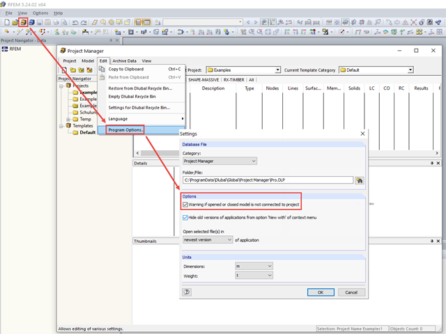
Warning Regarding Connection to Project
---
When opening a model immediately after opening the program, there is a message window asking if you want to create a new project for the model in the Project Manager.
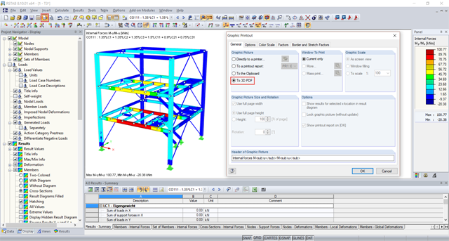
The 3D PDF functionality allows you to display three-dimensional models from RFEM or RSTAB in a 3D PDF.

In RF-/STEEL EC3, sets of members are calculated according to the General Method (EN 1993-1-1, Cl. 6.3.4) together with the stability analysis. To do this, it is necessary to determine the correct support conditions for the equivalent structure with four degrees of freedom. In most 3D models today, you can quickly lose track of the location of a set of members in the system.
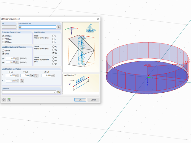
In RFEM, loads can be freely defined on surfaces. It is impossible, however, to define a variable loading on, for example, circular surfaces. However, you can still create this type of loading by using a free circular load.

With the orthotropic elastic-plastic material model, you can calculate solids with plastic material properties in RFEM 5 and evaluate them according to the Tsai‑Wu failure criterion. The Tsai-Wu criterion is named for Stephen W. Tsai and Edward M. Wu, who published it in 1971 for plane stress states.

In RFEM 6, seismic analysis can be done by using the Modal Analysis and the Response Spectrum Analysis add-ons. Once the spectral analysis has been performed, it is possible to use the Building Model add-on to display story actions, interstory drifts, and forces in shear walls.
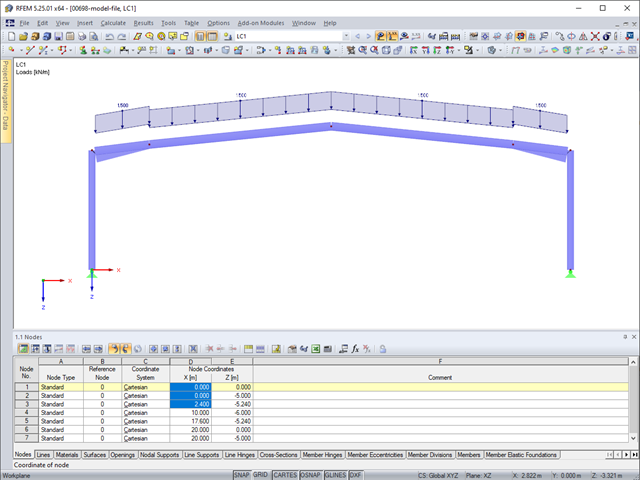
You can use the selection functions to facilitate the input in the tables.

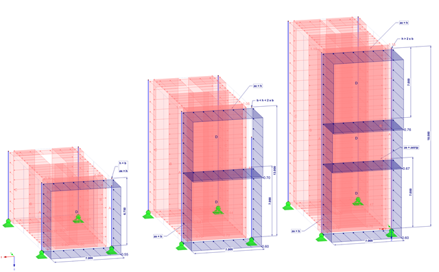
The new "Result Beam" member type in RFEM 5 allows you to determine the load sums of individual floors easily. To do this, model a member in the relevant floor or in all floors, then specify the relevant walls as inclusive objects in the parameters of the result beam. RFEM then integrates the surface internal forces into member internal forces.
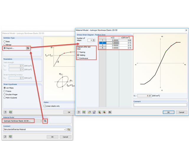
With the nonlinear elastic material model in RFEM 5, you can calculate and carry out a stress analysis of surfaces and solids with nonlinear material properties.
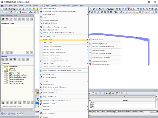
The model check allows you to search for discrepancies occurring during the modeling.
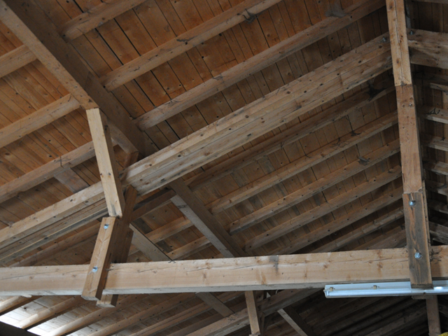
When modeling frame structures, RFEM and RSTAB provide various options for controlling the transfer of internal forces and moments at the connection points of members. You can use the member types to determine whether only forces act on the connected members, or whether moments act on them as well. In addition, you can use hinges to exclude specific internal forces from the transfer. One special form is scissor hinges, which allow for realistic modeling of roof structures, for example.

To simulate a support clearance in a connection between members, you can use the "Diagram" function for member hinges. To use this function, first define the relevant degree of freedom as release. Then, you can select the "Diagram" function from the drop‑down list.
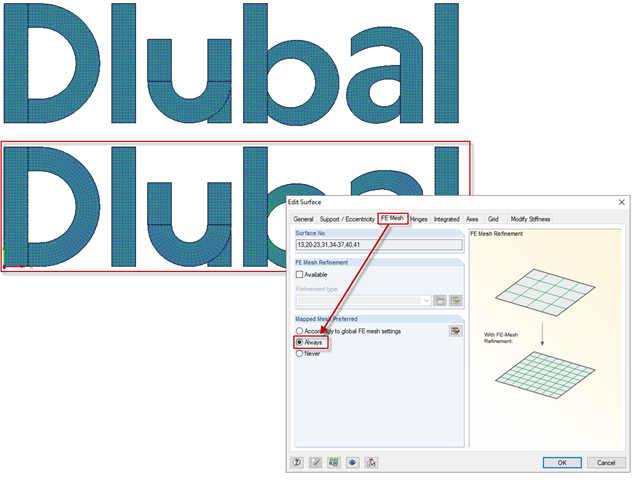
The "Mapped Mesh Preferred" option has an influence on the mesh generation of surfaces with curved and folded outlines. The program tries to align the FE mesh with the boundary lines of the surfaces.

This article explains the use of surfaces with the Load Transfer stiffness type in RFEM 6. A practical example is also provided to demonstrate the application of self-weight, snow load, and wind load to a steel hall.

For foundation design, it is necessary to define the relevant loads for the respective design situations (STR, GEO, UPL, EQU).

You can use the "Free Circular Load" option in RFEM to apply a partial uplift force to a cone‑shaped floor slab. It can be defined as linearly variable. The definition of center C and the outer boundary R can be specified easily, using the select function.